+86 186 7553 4520
 jiayonghuang03@gmail.com


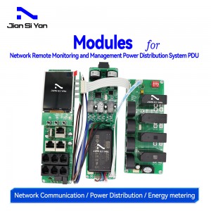
Single-phase and Three-phase IP PDU Meters for Network Remote Monitoring and Management Power Distribution System

2. Product Introduction
2.2 Function introduction
|
Performance parameters |
Technical indicators |
|||||
|
Electrical parameters |
Input Optional |
Single Phase |
Input voltage | 176-264V | ||
|
|
Maximum total load current | 63A | ||||
|
Three-phase |
Input voltage | 3*220V 50Hz | ||||
| Maximum total load current | 3*32A Optional 63A, 120A, 150A | |||||
| Output | Output Voltage | 176-264V | ||||
| Output Current | 8A, optional high current 20A | |||||
| Output Port | Optional, up to 36 ports | |||||
| Frequency | 50Hz | |||||
|
User interface |
Display | TFT color screen | ||||
| Operation buttons | Up, down, set, reset buttons | |||||
| Communication interface | One Ethernet, two RS485 | |||||
| Temperature and humidity interface | Two | |||||
| Switch input interface | Two interfaces, 4 channels | |||||
| Switch output interface | One interface,2 channels | |||||
|
Electrical parameter measurement |
PDU total measurement | Voltage, current, power, electric energy | ||||
| Each output measurement | Voltage, current, power, electric energy | |||||
| Each output can be remotely turned on/off | Yes | |||||
| Customize the power-on/power-off sequence and interval time for each output | Yes | |||||
| Administrator permissions can be defined in different levels | Yes | |||||
| Customize alarm signal thresholds | Voltage and current adjustable | |||||
| Cascade function | Yes, 4 products can be cascaded | |||||
|
Monitoring function |
Load current monitoring | |||||
| Load power monitoring | ||||||
| Voltage monitoring | ||||||
|
|
Power monitoring | |||||
|
|
Ambient temperature and humidity monitoring | |||||
|
Setting the function |
Load current upper and lower limit settings | |||||
|
|
Ambient temperature and humidity upper and lower limit settings | |||||
|
|
Email alert address settings | |||||
|
|
SNMP (V1, V2c,V3) settings | |||||
|
|
Network parameter settings (IP, gateway, mask, DNS ) | |||||
|
Alarm function |
system Alerts |
When the load current exceeds the rated value | ||||
|
|
|
When the temperature and humidity exceed the limit | ||||
|
|
Custom Alerts |
When the load current exceeds the rated value | ||||
|
|
|
When the temperature and humidity exceed the limit | ||||
|
|
Alerts Way |
Buzzer beeps | ||||
| LCD value flashes | ||||||
| Automatically send an email to the system administrator | ||||||
| SNMP sends Trap alarm status information | ||||||
| Serial communication background sends alarm status information | ||||||
| Access method | WEB access and control through IE | |||||
| SNMP (V1,V2c,V3) access and control via standard network management workstation | ||||||
| User Management | User ID and password settings | |||||
| environment | Operating temperature | -20 ~ 60℃ | ||||
| Extreme operating temperature | -30 ~ 70℃ | |||||
| Relative humidity | 10 ~ 90% | |||||
| Storage and transportation temperature limit | -40 ~ 70℃ | |||||
2.3 Model selection
◆ MK-352IP stands for intelligent PDU meter head.
3. Main functions
3.1 Real-time monitoring function
3.2 Socket unit control
◆ Control the closing and opening of a single relay, or control multiple relays simultaneously.
3.3 Customized alerts
◆ The total load current/voltage over-limit threshold can be customized, the load current over-limit threshold of each socket unit can be customized, and the temperature/humidity over-limit threshold can be customized.
3.4 Master-slave (cascade) communication

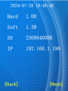
4.1 User interface and parameters

4.2 Product size
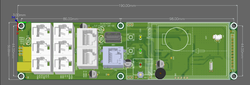
JSY-MK-352 IP Intelligent PDU Meter Dimensions.
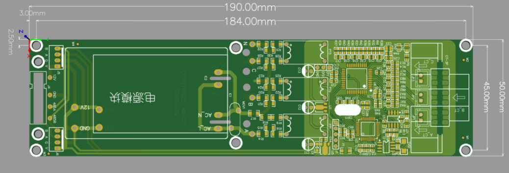
JSY-MK-352AFE three-phase four-wire power module dimensions
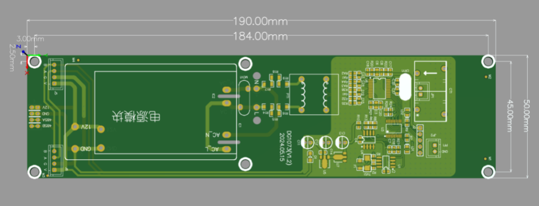
JSY1073 single-phase power module dimensions
JSY1054 4-channel relay control module dimensions

JSY1084 4-channel relay control module dimensions

5. Web Network Operation
5.1 Supported browsers
5.2 Cascade Setting Instructions
◆ You can use the PDU's system IP address as the URL of the web interface and log in using a case-sensitive username and password.
5.2.1 Cascade settings
1.1.1 Log in
As shown

The default username and password for the super administrator is: " admin", then click Login. as shown in Figure 5.2.2: